


























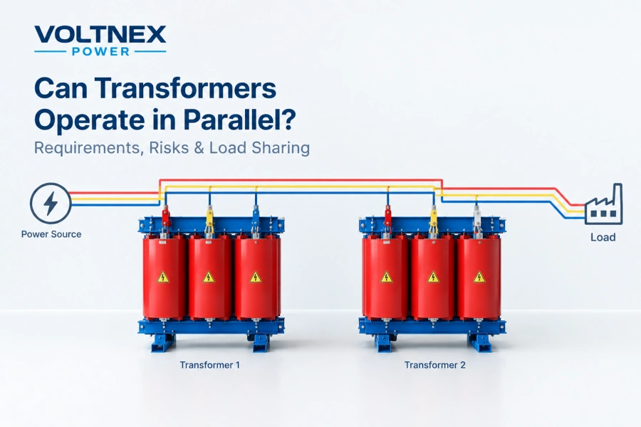
Connecting two or more transformers in parallel can increase power capacity, improve system reliability, and provide flexibility for future expansion. However, transformers cannot be connected in parallel simply because they have the same voltage rating. Their electrical characteristics and operating conditions must be compatible.
For industrial facilities, commercial buildings, manufacturing plants, and power distribution systems, understanding transformer paralleling requirements is essential for safe and reliable operation.
This guide explains the main requirements, common risks, load-sharing principles, and key considerations when selecting transformers for parallel operation.
1. What Is Parallel Operation of Transformers?
Transformer parallel operation means connecting the primary windings of two or more transformers to a common power supply and connecting their secondary windings to the same load bus.
When properly designed, the transformers share the total load instead of relying on a single unit.
For example, two 500 kVA transformers may operate in parallel to supply a combined load approaching 1,000 kVA, provided that the transformers, protection systems, and installation are designed for this operating condition.
Typical benefits include:
-
Increased capacity: Support higher electrical loads.
-
Improved reliability: Allow one transformer to be isolated for maintenance when the system is designed with suitable redundancy.
-
Flexible expansion: Add transformer capacity as demand grows.
-
Operational flexibility: Distribute loads across multiple units.
However, actual usable capacity depends on transformer compatibility, load characteristics, cooling conditions, protection settings, and the required reserve capacity.
2. Key Requirements for Parallel Transformer Operation
2.1 Matching Voltage Ratios
Transformers should have compatible primary-to-secondary voltage ratios and suitable tap settings.
If their secondary voltages differ, circulating current may flow between the transformers even when the external load is small. This current creates additional losses and heating.
For example, two transformers designed for the same nominal input and output voltages may still have different actual secondary voltages because of tap positions or manufacturing characteristics.
Before parallel operation, verify the rated voltage ratios, tap positions, and actual secondary voltages.
2.2 Compatible Phase Sequence and Phase Displacement
For three-phase transformers, the phase sequence and phase displacement must be compatible.
Transformers with incompatible phase relationships can produce severe circulating currents or an electrical short circuit when their secondary windings are connected together.
The vector group identifies the winding connections and phase displacement. Common examples include Dyn11 and Yyn0.
Transformers with different vector groups should not be paralleled unless an engineered arrangement has been verified to provide the required electrical compatibility. Matching nominal voltages alone is not sufficient.
2.3 Compatible Winding Connections
Winding configurations, neutral arrangements, and grounding methods must suit the intended system.
For example, a delta-wye transformer and a wye-wye transformer may have different phase relationships and zero-sequence characteristics. These differences can affect circulating currents, grounding behavior, and protection operation.
Engineers should confirm the vector group, neutral availability, grounding design, and system requirements before approving a parallel connection.
2.4 Similar Percentage Impedance
Transformer impedance is one of the most important factors affecting load sharing.
Percentage impedance represents the impedance of a transformer relative to its rated operating conditions. When transformers operate in parallel, their impedances influence how much load each unit carries.
If their impedances differ significantly, the lower-impedance transformer generally carries a greater share of the load relative to its rating. It may become overloaded even when the combined load is below the total rated capacity.
For reliable load sharing, transformers should have compatible percentage impedance values and impedance characteristics, subject to their ratings and system design.
2.5 Compatible Frequency and Rated Capacity
Transformers must be suitable for the same system frequency and operating voltage.
Different rated capacities can operate in parallel, but load sharing must be evaluated according to each unit’s impedance and rating. Simply adding the kVA ratings does not guarantee that each transformer will remain within its limits.
For example, a 500 kVA transformer and a 1,000 kVA transformer may be suitable for parallel operation if their electrical characteristics and protection arrangements are compatible.
3. How Do Parallel Transformers Share the Load?
Under suitable conditions, transformers share load according to their impedances and rated capacities.
For transformers with the same voltage ratio and compatible phase relationships, the unit with lower impedance relative to its rating tends to carry more load.
When two transformers have identical percentage impedance and compatible characteristics, their load sharing is approximately proportional to their kVA ratings.
For example, two 500 kVA transformers with matching impedance characteristics supplying a total load of 800 kVA would each carry approximately 400 kVA.
If one transformer has a substantially lower percentage impedance, the load distribution may become unequal. The lower-impedance unit may reach its rated capacity before the other transformer does.
Engineers should calculate expected load sharing using transformer ratings and impedance data, then verify that neither unit exceeds its permitted operating limits.
4. Common Risks of Incorrect Parallel Operation
Incorrectly paralleling transformers can lead to several serious problems.
Circulating currents: Voltage-ratio differences or incompatible phase relationships can cause current to flow between transformers, increasing losses and temperature.
Transformer overloading: Unequal impedance can cause one unit to carry excessive current, even if the combined load appears acceptable.
Short-circuit stress: Parallel operation increases the available fault current at the common bus in many installations. Switchgear, circuit breakers, busbars, and cables must be rated for the resulting fault level.
Protection coordination problems: Existing protective devices may not operate correctly when transformers are added in parallel. Protection settings and selectivity must be reviewed.
Reduced service life: Excessive heating and repeated overloading can accelerate insulation deterioration and reduce transformer service life.
These risks make engineering review, electrical testing, and coordinated protection essential before energizing a parallel transformer system.
5. Transformer Paralleling Checklist
Before connecting transformers in parallel, verify the following:
-
Primary and secondary voltage ratings and voltage ratios are compatible.
-
Tap positions and actual secondary voltages are suitable.
-
Three-phase units have compatible phase sequence and phase displacement.
-
Vector groups and winding connections are compatible.
-
Percentage impedance and load-sharing characteristics are suitable.
-
Rated frequencies and operating conditions are compatible.
-
Neutral and grounding arrangements meet system requirements.
-
Short-circuit ratings and protection coordination have been checked.
-
Manufacturer documentation and commissioning tests have been reviewed.
Parallel operation should be approved by qualified electrical engineers and performed according to the applicable standards, manufacturer instructions, and site safety procedures.
6. How to Select Transformers for Parallel Operation
If a project requires multiple transformers, it is best to consider parallel operation during the initial design stage rather than after the equipment has been installed.
Provide the transformer manufacturer with the required total capacity, primary and secondary voltages, phase configuration, frequency, vector group, percentage impedance, installation environment, and expected load profile.
For projects involving future expansion, specifying compatible electrical characteristics across all units can make later capacity upgrades easier and safer.
Voltnex Power provides industrial transformer solutions for voltage conversion and customized power distribution applications. Transformer selection can be tailored to project requirements, subject to technical review and confirmation of compatibility for parallel operation.
Conclusion
Transformers can operate in parallel when their voltage ratios, phase relationships, winding connections, impedance characteristics, and protection arrangements are compatible.
The most important consideration is not simply whether the transformers have the same voltage rating, but whether they can share the load safely without excessive circulating current, overloading, or unacceptable fault levels.
Careful specification, engineering calculations, and commissioning checks help ensure reliable parallel operation in industrial and commercial power systems.
Need transformers for an industrial project? Contact Voltnex Power with your required capacity, voltage ratings, phase configuration, and application to discuss a suitable transformer solution.