

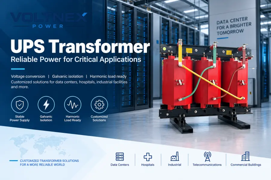
A UPS transformer is a specially designed transformer used with an Uninterruptible Power Supply (UPS) system to provide voltage conversion, electrical isolation, grounding configuration, and reliable power distribution for critical electrical loads.
UPS transformers are commonly installed in data centers, hospitals, telecommunications facilities, industrial plants, control systems, financial facilities, laboratories, transportation infrastructure, and other mission-critical power systems where reliable and stable electrical power is essential.
Depending on the UPS topology and electrical distribution system, the transformer may be installed at the UPS input, UPS output, bypass circuit, or downstream distribution system.
However, selecting a UPS transformer involves much more than simply matching the kVA rating.
Engineers must consider:
- UPS input and output voltage
- Transformer capacity
- Single-phase or three-phase configuration
- Frequency
- Isolation requirements
- Winding connection
- Neutral and grounding requirements
- Harmonic loading
- K-factor
- Short-circuit impedance
- Inrush current
- Insulation class
- Cooling method
- Enclosure protection
- Ambient temperature
- Installation altitude
- Applicable IEC or IEEE standards
This guide explains how UPS transformers work, the different transformer configurations used in UPS systems, how to calculate transformer capacity, and how to select the correct transformer for industrial and commercial UPS applications.
What Is a UPS Transformer?
A UPS transformer is a transformer specifically selected or engineered to operate as part of an Uninterruptible Power Supply electrical system.
Its primary purpose depends on where the transformer is installed.
A UPS transformer may be used to:
- Step voltage up or down
- Provide galvanic isolation
- Establish a new neutral point
- Change the grounding arrangement
- Adapt utility voltage to UPS input voltage
- Adapt UPS output voltage to load voltage
- Handle nonlinear and harmonic-rich loads
- Reduce common-mode electrical noise
- Improve compatibility between the UPS and downstream electrical distribution system
For example, an industrial facility may have a 480 V three-phase electrical supply, while the critical equipment requires a 208Y/120 V distribution system.
A UPS output transformer can convert:
480 V → 208Y/120 V
while simultaneously providing an independently derived secondary neutral when the transformer and grounding arrangement are designed accordingly.
Similarly, a transformer can be installed upstream of a UPS when the available utility voltage does not match the required UPS input voltage.
How Does a UPS Transformer Work?
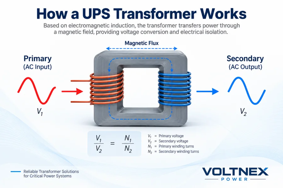
A UPS transformer operates according to the same electromagnetic induction principle as a conventional power transformer.
AC voltage applied to the primary winding produces alternating magnetic flux in the transformer core. This magnetic flux induces voltage in the secondary winding.
The voltage relationship is approximately:
V₁ / V₂ = N₁ / N₂
where:
- V₁ = Primary voltage
- V₂ = Secondary voltage
- N₁ = Primary winding turns
- N₂ = Secondary winding turns
Changing the winding turns ratio allows the transformer to increase, decrease, or maintain the voltage.
For example:
480 V → 208Y/120 V
provides voltage reduction.
A:
400 V → 400 V
transformer may have a 1:1 voltage ratio but can still be used where galvanic isolation, neutral creation, or grounding separation is required.
This is why a UPS transformer should not simply be considered a voltage converter.
Its function depends on the complete UPS electrical architecture.
Main Functions of a UPS Transformer
1. Voltage Conversion
Voltage conversion is one of the most common reasons for installing a transformer with a UPS.
Electrical supply standards vary between countries, industrial facilities, and equipment.
Typical UPS transformer voltage combinations include:
Both standard and customized voltage ratios can be manufactured according to the electrical system requirements.
2. Galvanic Isolation
A true isolation transformer uses electrically separate primary and secondary windings.
There is no direct conductive connection between the two windings.
Instead, energy is transferred magnetically through the transformer core.
This can help provide electrical separation between circuits and can be useful for:
- Sensitive electronic equipment
- Data center electrical systems
- Industrial control equipment
- Laboratory equipment
- Telecommunications systems
- Instrumentation
- Critical process control systems
However, an important distinction must be made:
A transformer-based UPS does not automatically mean that the entire UPS system has complete input-to-output galvanic isolation.
The actual isolation depends on the UPS topology, bypass arrangement, transformer position, neutral configuration, and grounding design.
When complete galvanic isolation is required, engineers must evaluate the entire electrical path rather than simply specifying a “transformer-based UPS.”
3. Neutral and Grounding Configuration
One of the most important reasons for adding an external UPS transformer is to establish the required neutral and grounding arrangement.
For example, a Delta-Wye transformer can provide:
480 V Delta → 208Y/120 V
The secondary Wye connection provides a neutral point that can be grounded according to the system design and applicable electrical regulations.
This can be particularly important for:
- Data centers
- Server rooms
- Telecommunications equipment
- Control systems
- Building electrical distribution
- Mixed line-to-line and line-to-neutral loads
Grounding design should always be coordinated with the UPS manufacturer, system designer, protection scheme, and local electrical code.
4. Electrical Noise and Common-Mode Interference
UPS systems frequently supply sensitive electronic loads.
Depending on transformer construction and system grounding, an isolation transformer can help reduce the transfer of certain common-mode electrical disturbances.
For applications requiring enhanced noise attenuation, an electrostatic shield can be installed between the primary and secondary windings.
The shield is normally connected to ground and helps reduce capacitive coupling between windings.
This configuration is commonly considered for:
- Data centers
- PLC systems
- CNC equipment
- Laboratory equipment
- Telecommunications equipment
- Measurement systems
- Sensitive industrial electronics
UPS Transformer vs Isolation Transformer
The terms UPS transformer and isolation transformer are sometimes used interchangeably, but they do not always describe exactly the same thing.
A UPS transformer describes the application of the transformer.
An isolation transformer describes an important electrical characteristic of the transformer.
Therefore, a UPS transformer can be:
- A step-down transformer
- A step-up transformer
- A 1:1 isolation transformer
- An input isolation transformer
- An output isolation transformer
- A harmonic-duty transformer
- A K-rated transformer
- A custom dry-type transformer
For many industrial UPS projects, several of these characteristics are combined into one transformer.
Where Is the Transformer Installed in a UPS System?
The position of the transformer significantly affects its function.
UPS Input Transformer
An input transformer is installed between the utility supply and the UPS input.
Typical configuration:
Utility → Transformer → UPS → Critical Load
It may be used for:
- Input voltage conversion
- Electrical system adaptation
- Grounding configuration
- Isolation where required by system design
Example:
Utility 480 V → Transformer 400 V → UPS 400 V
UPS Output Transformer
An output transformer is installed downstream of the UPS.
Typical configuration:
Utility → UPS → Transformer → Critical Load
This arrangement is commonly used when the UPS output voltage differs from the required load voltage.
Example:
UPS 480 V → Transformer → 208Y/120 V Critical Load
The output transformer can also establish a new secondary neutral and grounding point when designed accordingly.
UPS Bypass Transformer
Some critical UPS architectures include a separate bypass power path.
Depending on the required isolation and grounding architecture, a transformer may also be required in the bypass circuit.
This is particularly important because installing a transformer only in the inverter path does not necessarily provide complete galvanic isolation when the load operates through bypass.
Therefore, engineers should evaluate:
Normal Mode + Battery Mode + Static Bypass Mode + Maintenance Bypass Mode
when determining the transformer arrangement.
Transformer-Based UPS vs Transformerless UPS
Modern UPS systems generally fall into two broad categories.
Transformer-Based UPS
Traditional industrial UPS systems may incorporate a transformer as part of their power conversion architecture.
Advantages can include:
- Robust electrical architecture
- Voltage transformation capability
- Certain grounding configuration options
- DC component isolation depending on topology
- Suitability for specific industrial applications
However, these systems are generally larger and heavier.
Transformerless UPS
Modern high-efficiency UPS systems frequently use transformerless power electronics.
Advantages include:
- Higher efficiency
- Smaller footprint
- Lower weight
- Reduced heat generation
- Easier modular expansion
A transformerless UPS does not mean that transformers can never be used.
Instead, an external UPS isolation transformer can be installed exactly where the electrical system requires voltage transformation, galvanic isolation, or neutral creation.
This approach is widely used in modern critical-power distribution systems.
UPS Transformer and Harmonic Loads
Harmonics are an important consideration when selecting transformers for UPS systems.
UPS rectifiers, inverters, server power supplies, variable-frequency drives, and other power-electronic equipment can behave as nonlinear loads.
Unlike a purely resistive linear load, nonlinear equipment may draw current in pulses.
The resulting current waveform can contain harmonic components such as:
- 3rd harmonic
- 5th harmonic
- 7th harmonic
- 9th harmonic
- 11th harmonic
- 13th harmonic
These harmonic currents can increase transformer losses and temperature rise.
Potential effects include:
- Increased winding losses
- Increased eddy-current losses
- Additional stray losses
- Neutral conductor heating
- Higher transformer operating temperature
- Reduced insulation life
- Reduced usable transformer capacity
For this reason, UPS transformer selection should consider the actual harmonic spectrum of the connected load.
What Is a K-Factor Transformer?
A K-factor transformer is designed to tolerate additional heating associated with nonlinear harmonic loads.
Common K-factor ratings include:
K-1, K-4, K-9, K-13, K-20 and higher project-specific requirements.
A conventional transformer may be sufficient for predominantly linear loads.
Where substantial nonlinear loads exist, however, the transformer may require special consideration for winding conductor size, eddy-current losses, thermal design, neutral loading, and harmonic spectrum.
UPS systems, server equipment, rectifiers, VFDs, and electronic power supplies are common examples of loads that may require harmonic evaluation.
The correct K-factor should not simply be selected by choosing the highest available rating.
It should be determined according to the expected or measured harmonic load.
For large UPS projects, provide the transformer manufacturer with:
- Load current
- THDi
- Harmonic spectrum
- UPS topology
- Rectifier type
- Power factor
- Crest factor if available
This allows the transformer to be properly designed for the actual operating conditions.
How to Size a UPS Transformer
Transformer sizing is one of the most important parts of UPS system design.
For a balanced three-phase system:
kVA = √3 × V × I / 1000
For a single-phase system:
kVA = V × I / 1000
If only load power in kW is known:
Required kVA ≈ Load kW / Power Factor
For example, assume a critical load is:
- Load power: 400 kW
- Power factor: 0.95
Then:
400 / 0.95 ≈ 421 kVA
A transformer should not automatically be selected at exactly 421 kVA.
Additional factors may include:
- Future expansion
- Continuous loading
- Harmonic losses
- Ambient temperature
- Installation altitude
- UPS overload characteristics
- Load diversity
- Inrush current
- Redundancy strategy
Depending on the engineering requirements, the project may therefore select the next suitable standard or customized transformer rating.
The final capacity should always be determined from the complete load profile rather than a fixed universal oversizing percentage.
Three-Phase UPS Transformer Selection Example
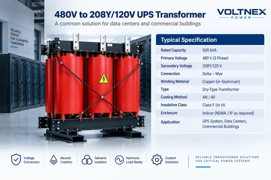
Consider a data center UPS system with the following requirements:
UPS output: 480 V, 3-phase, 60 Hz
Required distribution voltage: 208Y/120 V
Transformer capacity: 500 kVA
Application: Data center IT loads
A possible transformer specification would be:
This type of transformer can provide voltage conversion while creating a Wye secondary neutral for downstream 120 V line-to-neutral IT and auxiliary loads.
Dry-Type vs Oil-Immersed UPS Transformer
Most low-voltage UPS isolation transformers are dry-type transformers, but larger power systems may also use oil-immersed transformers depending on voltage, capacity, location, and project architecture.
Dry-Type UPS Transformer
Dry-type transformers are commonly selected for indoor UPS rooms and electrical rooms.
Typical advantages include:
- No insulating oil
- Suitable for indoor installation
- Lower liquid-fire risk
- Convenient maintenance
- Flexible enclosure design
- Suitable for data centers and commercial buildings
Typical applications include:
UPS rooms, data centers, hospitals, telecom facilities, factories and commercial buildings.
Oil-Immersed Transformer
Oil-immersed transformers may be used for larger distribution systems or where medium-voltage transformation is required upstream of the UPS system.
Typical applications include:
- Large industrial plants
- Utility-fed facilities
- Large data centers
- Medium-voltage distribution
- Outdoor substations
For example:
10 kV / 0.4 kV
or
13.8 kV / 480 V
transformers may supply a large low-voltage UPS distribution system.
Copper vs Aluminum Windings
Both copper and aluminum can be used for transformer windings when properly engineered.
Copper Windings
Copper provides high electrical conductivity and allows compact conductor designs.
It is commonly specified for:
- Data centers
- Industrial UPS systems
- Critical infrastructure
- High-current applications
- Projects where copper is explicitly required by specification
Aluminum Windings
Aluminum can provide a more economical solution while maintaining reliable transformer performance when properly designed.
Selection should therefore be based on:
- Project specification
- Physical size
- Current density
- Thermal design
- Cost
- Customer preference
rather than assuming that winding material alone determines transformer quality.
Important UPS Transformer Specifications
When requesting a quotation for a UPS transformer, provide as much of the following information as possible:
For special applications, also provide harmonic spectrum, THDi, UPS manufacturer/model, load type, grounding requirements, short-circuit level, and environmental conditions.
Common UPS Transformer Applications
Data Centers
UPS transformers are widely used in:
- Enterprise data centers
- Hyperscale data centers
- AI data centers
- Cloud computing facilities
- Server rooms
- Colocation facilities
They can provide voltage transformation and electrical distribution between UPS outputs, PDUs, switchboards, and critical IT loads.
Hospitals and Healthcare Facilities
UPS systems support critical hospital electrical loads such as:
- Medical equipment
- Monitoring systems
- Laboratory equipment
- Emergency systems
- Critical IT infrastructure
Transformer requirements in healthcare facilities can be highly application-specific and should follow applicable medical electrical and local safety standards.
Industrial Automation
Factories use UPS transformers to support:
- PLC systems
- DCS systems
- Industrial computers
- Control panels
- Instrumentation
- Automation equipment
- Process control systems
These systems often require reliable operation despite disturbances in the main industrial electrical network.
Telecommunications
Telecommunications infrastructure relies heavily on uninterrupted power.
UPS transformers may be used in:
- Telecom switching facilities
- Communication equipment rooms
- Broadcasting facilities
- Network operation centers
- Base-station infrastructure
Banking and Financial Infrastructure
Banks, exchanges, transaction systems, and financial data centers require extremely high electrical availability.
UPS transformers can form part of the redundant power architecture protecting these mission-critical systems.
How to Choose the Right UPS Transformer
Before purchasing a UPS transformer, answer these questions:
- What is the available input voltage?
- What voltage does the UPS or load require?
- What is the required transformer capacity in kVA?
- Is the system single-phase or three-phase?
- Is the frequency 50 Hz or 60 Hz?
- Is galvanic isolation required?
- Is a new secondary neutral required?
- What grounding arrangement is required?
- What is the expected harmonic spectrum or THDi?
- Is a K-rated design required?
- What transformer impedance is required?
- Is an electrostatic shield required?
- Is the transformer installed indoors or outdoors?
- What enclosure protection level is required?
- What are the maximum ambient temperature and installation altitude?
- Which IEC, IEEE, ANSI, UL, CSA, or local standards apply?
Providing these parameters allows the manufacturer to select or design the transformer much more accurately.
UPS Transformer Manufacturer
Voltnex Power manufactures customized power and distribution transformer solutions for industrial, commercial, data center, renewable energy, and infrastructure projects.
Our transformer manufacturing capability covers a wide range of voltage classes and capacities, including customized transformer designs for international projects.
Available solutions include:
- Three-phase UPS isolation transformers
- Dry-type isolation transformers
- K-factor transformers
- Harmonic-duty transformers
- Step-up transformers
- Step-down transformers
- Three-phase dry-type transformers
- Oil-immersed distribution transformers
- Medium-voltage transformers
- Pad-mounted transformers
- Substation transformers
- Customized industrial transformers
Transformer designs can be configured according to project requirements for:
Voltage ratio, capacity, frequency, vector group, winding material, impedance, insulation class, cooling method, enclosure, protection level, harmonic loading, installation environment and applicable standards.
Voltnex Power supports transformer projects designed according to applicable IEC, IEEE/ANSI, UL and CSA requirements, depending on product type and project specifications.
For a UPS transformer quotation, customers can provide the UPS model, rated power, input/output voltage, load type, harmonic information, installation environment, and required standards for technical evaluation.
Frequently Asked Questions About UPS Transformers
What is a UPS transformer?
A UPS transformer is a transformer installed within or alongside an Uninterruptible Power Supply system for voltage transformation, isolation, grounding configuration, neutral creation, or critical-load power distribution.
Does every UPS need an isolation transformer?
No.
Many modern transformerless UPS systems operate without a dedicated isolation transformer. An external transformer is added when the electrical system requires functions such as voltage conversion, galvanic isolation, neutral creation, or a specific grounding configuration.
Can a UPS transformer step 480 V down to 208Y/120 V?
Yes.
A three-phase transformer can be designed with a 480 V primary and 208Y/120 V secondary. Delta-Wye is a common configuration when a secondary neutral is required.
Can a UPS transformer be 1:1?
Yes.
A transformer such as 400 V / 400 V or 480 V / 480 V can use separate primary and secondary windings while maintaining the same nominal voltage.
This configuration is commonly called a 1:1 isolation transformer.
What is a K-13 UPS transformer?
A K-13 transformer is designed to accommodate a specified level of additional heating associated with nonlinear harmonic loads.
Whether K-13 is appropriate should be determined from the expected harmonic spectrum and system design rather than selected automatically for every UPS.
Should I use copper or aluminum windings?
Both materials can provide reliable operation when the transformer is correctly designed.
Copper is frequently specified for critical UPS and data center applications, while aluminum can provide a cost-effective alternative for suitable projects.
What size transformer do I need for a UPS?
Transformer capacity depends on the UPS rating, actual load, power factor, harmonic content, overload requirement, future expansion, ambient conditions, and system architecture.
For three-phase systems, basic apparent power can be calculated using:
kVA = √3 × Voltage × Current / 1000
The final transformer rating should be selected after evaluating the complete UPS and load profile.
What information should I send to a UPS transformer manufacturer?
At minimum, provide:
Capacity (kVA), primary voltage, secondary voltage, phase, frequency, winding material, application, installation environment and quantity.
For engineering projects, also provide the UPS datasheet, harmonic data, grounding requirements, impedance, enclosure rating, ambient temperature, altitude and applicable standards.
Conclusion
A UPS transformer is not simply an accessory added to an Uninterruptible Power Supply.
Depending on the electrical architecture, it can provide voltage conversion, galvanic isolation, neutral creation, grounding configuration, harmonic-load capability and reliable distribution of power to critical equipment.
The correct transformer therefore depends on the entire UPS system.
For a small commercial UPS, a simple low-voltage isolation transformer may be sufficient. For a large data center or industrial UPS installation, transformer selection may require detailed evaluation of kVA capacity, voltage ratio, winding configuration, harmonic spectrum, K-factor, impedance, grounding, cooling, insulation, environmental conditions and applicable electrical standards.
When specifying a customized UPS transformer, provide the transformer manufacturer with the UPS datasheet and complete electrical system requirements whenever possible.
This allows the transformer to be engineered around the actual operating conditions rather than selected only by nominal voltage and kVA.
Voltnex Power provides customized transformer solutions for UPS systems, data centers, industrial facilities and critical power infrastructure worldwide.