

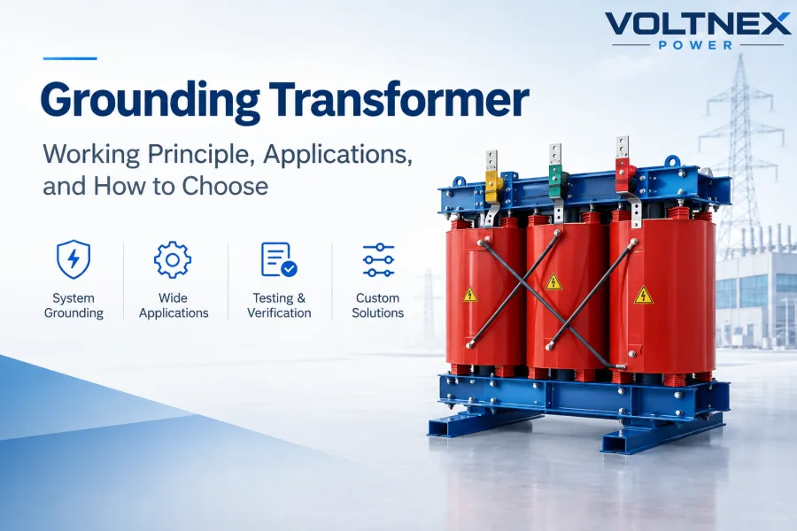
A grounding transformer, also called an earthing transformer or neutral grounding transformer, is a special-purpose transformer used to create a neutral point and provide a controlled path for zero-sequence and ground-fault current in a three-phase power system.
It is especially important in ungrounded or delta-connected systems where a natural neutral point is not available. By establishing an artificial neutral, a grounding transformer can help control ground-fault current, stabilize the system neutral, reduce transient overvoltages and allow protection equipment to detect and clear faults more effectively.
Grounding transformers are widely used in solar PV plants, wind farms, battery energy storage systems, generators, industrial power systems and utility substations.
What Is a Grounding Transformer?
A grounding transformer is not primarily designed to supply a large continuous electrical load like a conventional distribution transformer.
Its main purpose is to provide a grounding point for a three-phase electrical system.
For example, a delta-connected system has three phase conductors but no accessible neutral. If the system needs a grounded neutral for fault protection, a grounding transformer can create an artificial neutral point.
The neutral of the grounding transformer can then be connected directly to ground or through a neutral grounding resistor (NGR), reactor or other impedance, depending on the grounding method and required fault-current level.
The grounding transformer therefore becomes part of the overall grounding and protection system rather than simply a voltage conversion device.
A properly designed grounding transformer can provide:
- An artificial neutral point
- A controlled zero-sequence current path
- Ground-fault current for protection systems
- Improved neutral stability
- Reduced transient overvoltage during ground faults
- A grounding connection for renewable-energy systems
Hammond Power Solutions notes that grounding transformers are particularly useful for three-phase three-wire systems and distributed generation systems such as solar, wind and generator installations.
How Does a Grounding Transformer Work?
The basic principle is electromagnetic induction, but the important part of grounding-transformer operation is its winding configuration and zero-sequence impedance.
During normal balanced three-phase operation, the currents in the three phases largely cancel each other in the zero-sequence path. As a result, the grounding transformer carries relatively little current.
When a line-to-ground fault occurs, however, zero-sequence current needs a return path.
The grounding transformer provides that path.
A typical system can be simplified as:
Three-Phase Power System → Grounding Transformer → Neutral Point → Ground / NGR → Fault Return Path
This allows the protection system to detect a controlled ground-fault current and operate the appropriate breaker or relay.
The grounding transformer is therefore designed around the required fault current, fault duration and zero-sequence impedance, rather than simply the normal load current.
This is one of the most important differences between a grounding transformer and a conventional power transformer.

Main Types of Grounding Transformers
Two common configurations are Zig-Zag grounding transformers and Wye-Delta grounding transformers.
1. Zig-Zag Grounding Transformer
The Zig-Zag grounding transformer is one of the most common grounding-transformer designs.
Its special winding arrangement creates an artificial neutral point while providing a relatively low-impedance path for zero-sequence current.
The Zig-Zag configuration is compact and is commonly selected when the primary purpose is system grounding rather than supplying a secondary load. HPS describes Zig-Zag units as a compact and cost-effective grounding solution.
Typical applications include:
- Solar PV power plants
- Wind power systems
- Battery energy storage
- Generator systems
- Industrial distribution networks
- Delta-connected systems
- Ungrounded three-phase systems
2. Wye-Delta Grounding Transformer
A Wye-Delta grounding transformer provides a grounded wye neutral and a delta winding.
Compared with a pure grounding-only configuration, a Wye-Delta design can also be used when an auxiliary three-phase load is required on the secondary side.
HPS identifies Wye-Delta as another common grounding-transformer configuration, with the secondary side available for suitable auxiliary loads.
The correct configuration depends on whether the project requires:
Grounding only
or
Grounding + auxiliary power
This distinction should be confirmed before the transformer is designed.
Where Are Grounding Transformers Used?
Grounding transformers are particularly useful in power systems where the source does not provide a usable neutral.
Solar PV Systems
Modern solar inverters may operate on three-phase systems without a solid neutral connection. A grounding transformer can provide an artificial neutral and a controlled grounding path.
This is especially important in large utility-scale solar farms and commercial PV systems.
Hammond Power Solutions specifically identifies solar, wind and other distributed energy resources as important grounding-transformer applications.
Wind Power Systems
Wind turbines and wind farms may use electrical systems where a grounding transformer is required to establish the desired neutral-grounding arrangement.
Battery Energy Storage Systems
BESS installations can also require a defined grounding strategy for the inverter and distribution system.
A grounding transformer can be integrated into the electrical system to establish the required neutral and fault-current path.
Generator Systems
Generators may use grounding transformers where the generator or connected distribution system does not have a suitable neutral connection.
Industrial Power Distribution
Manufacturing plants, mining facilities, petrochemical installations and other industrial systems may use grounding transformers to improve ground-fault protection and system stability.
Grounding Transformer vs Conventional Transformer
A grounding transformer should not be selected in the same way as an ordinary distribution transformer.
One particularly important point is that a grounding transformer may not be sized simply by its apparent-power rating.
HPS states that grounding transformers are generally not sized by kVA because little current flows through the windings during normal operation; the short-duration fault current and duration are major design factors.

How to Specify a Grounding Transformer
If you are requesting a quotation for a grounding transformer, simply providing the system voltage is usually not enough.
A manufacturer normally needs several important electrical parameters.
1. System Voltage
Provide the line-to-line voltage of the three-phase system.
Examples:
480V, 600V, 4.16kV, 6.6kV, 11kV, 13.8kV, 33kV
The actual voltage class determines the insulation and transformer design.
2. Ground-Fault Current
Specify the required ground-fault current.
For example:
400A for 10 seconds
or
1000A for 5 seconds
The actual value must be determined from the system grounding study and protection requirements.
3. Fault Duration
Grounding transformers often operate under fault conditions for a limited period until the protection system clears the fault.
Typical project specifications may use a short-time duration such as several seconds, but the actual duration must be specified by the system designer.
4. Continuous Neutral Current
Although the transformer may carry little current during a perfectly balanced condition, real systems can have continuous neutral current caused by system imbalance and other conditions.
The continuous rating therefore needs to be considered separately from the short-time fault rating.
5. Zero-Sequence Impedance
This is one of the most important parameters in grounding-transformer design.
The required zero-sequence impedance determines how the grounding transformer behaves during a ground fault and helps establish the desired fault-current level.
6. Connection
Specify whether the project requires:
- Zig-Zag
- Wye-Delta
- Grounding transformer with auxiliary winding
- Grounding transformer with NGR/reactor connection
7. Installation Conditions
The manufacturer may also need:
- Indoor or outdoor installation
- Ambient temperature
- Enclosure type
- Altitude
- Insulation level / BIL
- Cooling method
- Frequency
- Copper or aluminum windings
- Required standards and certifications
HPS’s grounding-transformer specification list similarly includes system voltage, BIL, continuous neutral current, fault current and duration, zero-sequence impedance, winding material, enclosure and environmental conditions.
Grounding Transformer Testing
Because a grounding transformer is part of a protection system, factory testing is particularly important.
Depending on the design, voltage class and customer specification, testing may include:
Winding Resistance Test
Measures the DC resistance of the windings and helps verify winding connections and electrical continuity.
Turns Ratio Test
Confirms the designed winding ratio and connection configuration.
Insulation Resistance Test
Checks the insulation condition between windings and between windings and ground.
Applied Voltage Test
Verifies the insulation system under the specified test voltage.
Induced Voltage Test
Tests the insulation between turns and winding sections under the specified induced-voltage condition.
Zero-Sequence Impedance Verification
For a grounding transformer, zero-sequence impedance is a critical design parameter and should be verified according to the project specification and applicable test procedure.
Short-Time Current Test
Where required by the specification, the transformer may need to demonstrate its ability to withstand the specified fault current for the required duration.
The exact factory test program should be determined according to the transformer’s voltage class, design, applicable standards and customer requirements rather than applying one identical test list to every grounding transformer.

Practical Case: Grounding Transformer for a Solar PV Plant
Consider a utility-scale solar PV plant using a three-phase inverter system without a directly available neutral.
The system operates normally with three phase conductors, but the electrical design requires a defined neutral grounding point for fault protection.
A suitable Zig-Zag grounding transformer can be installed at the appropriate point in the system.
The basic arrangement can be represented as:
PV Inverters → Medium-Voltage Collection System → Grounding Transformer → Neutral → Ground / NGR
During normal balanced operation, the grounding transformer carries relatively little current.
If a phase-to-ground fault occurs, the grounding transformer provides the zero-sequence path required by the grounding design. The resulting controlled fault current allows the protection system to detect the abnormal condition and disconnect the affected circuit.
The exact transformer rating cannot be determined from the PV plant’s MW rating alone. The system voltage, required ground-fault current, fault duration, zero-sequence impedance and continuous neutral current must be considered.
This is why grounding-transformer design should be based on the electrical protection study, not simply the total generation capacity.
Custom Grounding Transformer Solutions
Every grounding system is different.
A transformer designed for a 480V industrial system may have completely different requirements from a grounding transformer for a 13.8kV solar farm or 33kV wind project.
Voltnex Power can develop customized grounding-transformer solutions according to the project’s electrical specifications.
Possible configurations include:
- Zig-Zag grounding transformers
- Wye-Delta grounding transformers
- Neutral grounding transformer systems
- Grounding transformers for PV and BESS
- Generator grounding transformers
- Industrial grounding transformers
- Custom neutral grounding solutions
Customization can include:
System voltage, fault current, fault duration, zero-sequence impedance, continuous neutral current, frequency, winding material, insulation level, enclosure, cooling and installation environment.
For OEM and project applications, the transformer can also be designed according to customer drawings, electrical specifications and required standards.
How to Choose the Right Grounding Transformer
Before contacting a manufacturer, prepare the following information:
System voltage: 480V / 600V / 4.16kV / 13.8kV / etc.
Frequency: 50Hz or 60Hz
System connection: Delta / Wye / Ungrounded
Grounding method: Solid / NGR / Reactor / Other
Ground-fault current: Required amperes
Fault duration: Seconds
Continuous neutral current: Amperes
Zero-sequence impedance: Ohms or specified value
Installation: Indoor / Outdoor
Environment: Ambient temperature, altitude and enclosure requirements
With these parameters, the transformer manufacturer can determine the appropriate grounding transformer configuration, winding design, impedance and short-time current capability.
If some parameters are unknown, an experienced transformer manufacturer can work with the system engineer to identify the missing information before quotation.
Grounding Transformer Manufacturer for Custom Industrial Applications
A grounding transformer is a relatively specialized transformer. The most important factor is not simply transformer size or price, but whether the electrical design matches the grounding and protection requirements of the system.
Voltnex Power provides custom industrial transformer solutions for solar PV, battery energy storage, generators, industrial power systems and other three-phase applications.
Whether you need a Zig-Zag grounding transformer, Wye-Delta grounding transformer or custom neutral grounding transformer, our engineering team can develop the transformer according to your system voltage, fault current, duration and grounding requirements.
Request a Custom Grounding Transformer Quote
Send us your:
System Voltage + Fault Current + Fault Duration + Continuous Neutral Current + Zero-Sequence Impedance + Frequency + Installation Environment
Our engineering team can review your requirements and provide a custom grounding transformer solution and factory quotation.
Need a Grounding Transformer for Your Project? Contact Voltnex Power → Request a Quote